Testing Power Electronics
Challenges of Power Electronic Testing
Why is the testing of power electronics regarded as a particular challenge?
Representing real conditions seems to be a hurdle for common test procedures. That is why we employ a different principle.
Challenges
Where is the serious flaw in common test procedures?
The question often asked in the quality testing of power electronics is, what needs to be “real” in the test layout, and what is deemed to be unnecessary.
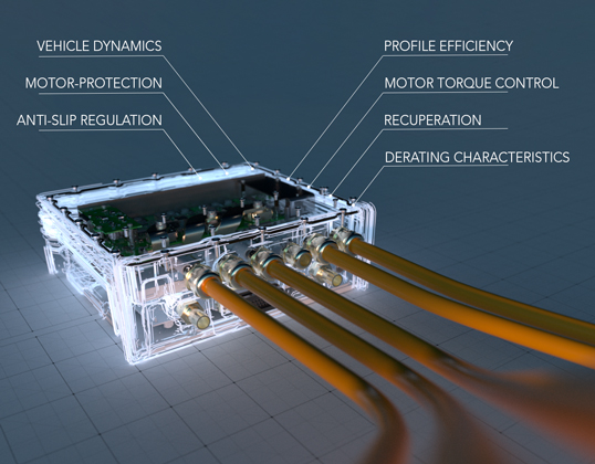
This question can be illustrated particularly well using the example of a drive inverter, a very complex piece of power electronics, but the principle applies to any form of power electronics:

The first thing to be done is to clarify which specification items are to be verified in which test layout. This involves the unit under test itself and also the required test environment. Due to the high levels of power, voltage and current that typically need to be controlled by a drive inverter, there is a tendency to completely do away with the power components of the device for the test process. The background is that off-the-shelf hardware-in-the-loop systems are only available for low level signals (Signal-HiL). The consequence is that the test layout is grossly simplified, however the test results obtained from such an approach lose massively in their meaningfulness.
The reason is that in order to conduct the test, the original unit-under-test has to be manipulated (“cracked ECU” procedure) and all unit-under-test components that come into contact with electrical power, high current levels or high voltages in any way are dismounted or deactivated. The functions lost by the unit-under-test as a result then have to be replaced with hardware and software models in order to “trick” the system into seeing a closed function.
In the case of an inverter, such an approach results in there being hardly any hardware left and the test object does not have a lot in common with the original unit to be tested and is often only a (manipulated) computer board.

Safety-relevant tests and hence qualified insights are not possible with this approach since the unit-under-test has lost its original character. This test approach can only provide sufficient answers to basic questions regarding computer architecture, software functions, or simple signal routing by the processor board. More profound validation tests on the entire power electronic module are not possible with this test layout.
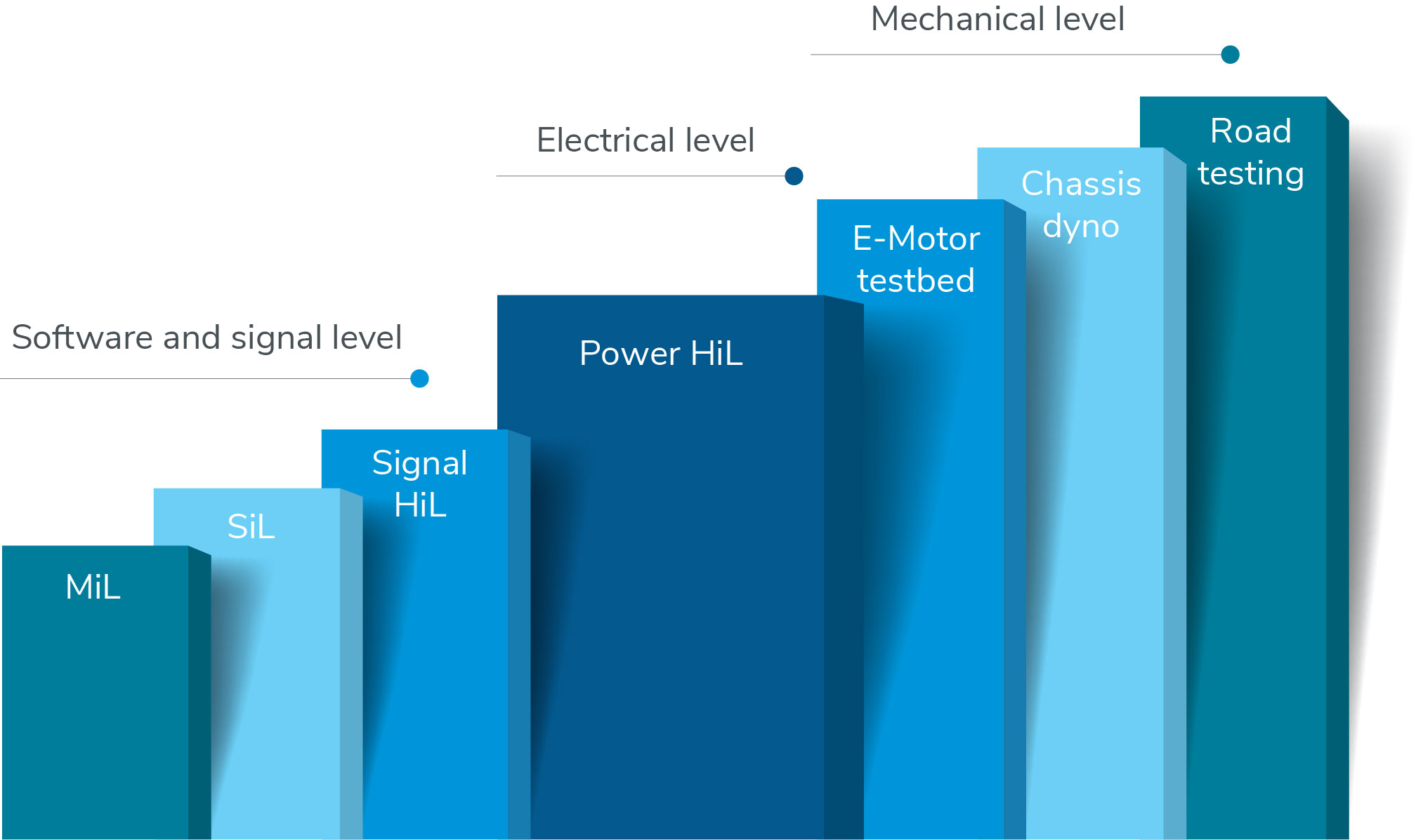
There is therefore a wide “gap” between these two approaches to testing. From a signal-HiL test layout to testing the inverter with a real motor is a huge step with many uncertainties. For your reassurance, we have overcome this test gap.
Instead of manipulation:
How can AVL SET help to close the testing gap?
A suitable test environment with sufficiently accurate conditions on the inverter’s interfaces must be designed in order to test the entire suite of power electronics, in our example the drive inverter, and to accompany development activities with the intention of validating hardware and software. This can be done by using the real high-voltage battery as a DC supply and the real e-motor on the phase connections, whereby the e-motor needs to be connected to a dynamometer to enable loading scenarios. Basically, a layout can also be considered where the dynamometer is replaced by a second e-motor as a loading device.
Testing is fundamentally divided between validation tests and production tests (end-of-line, EOL). Lifetime tests are a subset of validation test. The testing of field returns after successful repair is a further test requirement, depending on the type of product and the manufacturing process. This is not a rerun qualification test (homologation). The solution here is often the use of the test system that was employed to qualify the product.
What challenges are to be expected when using real components
And our solution
Battery
If real components such as the battery and e-motor are used, then the mechanical layout represents a significant danger, particularly because of the battery, introduces ageing effects, thermal issues, states of charge, and many more undesirable side-effects. The consequence? We replace the real battery when testing the power electronics with an emulated battery, a so-called battery emulator.
For systems that use a fuel cell as an energy source, the fuel cell is replaced by a suitable DC current source. Similarly, the same issues occur on the AC side of the drive inverter. A real e-motor has to be suitably loaded, has production tolerances, displays thermal effects, is subject to wear, in other words many side-effects that are undesirable when testing power electronics.
In addition, the e-motor is often not available in time, because it is still under development or there are only individual prototypes.
E-Motor
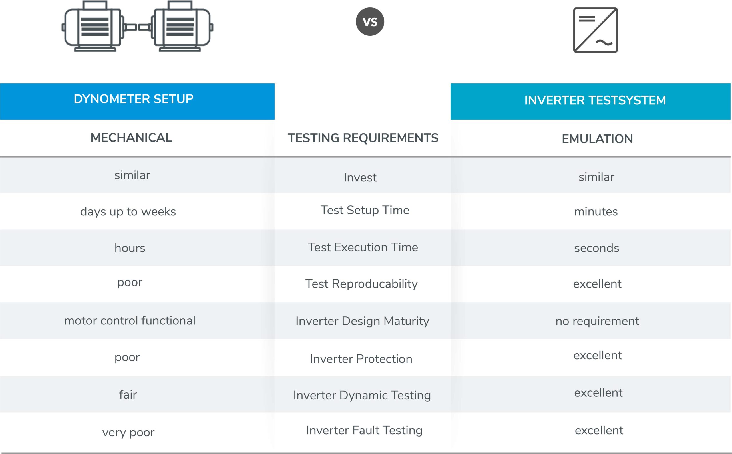
The central issue when testing with a real e-motor is however that the integration of inverter and e-motor must occur at a point in time where just the power electronics are to be tested independently of the e-motor. This mixes two levels of complexity: The electrical level of the inverter with the mechanical level of the e-motor.
Inverter testing becomes time-consuming and unnecessarily complex, and still only permits an incomplete test depth. Conducting tests of reactions to faults using such a mechanical layout is insufficient. Added to this is the fact that a dynamometer can only display a limited control dynamic response and, for example, load torques at very low speeds tend to oscillate.
A functioning motor controller must be first implemented on the inverter side for initial testing to be conducted without damaging the unit-under-test or the e-motor.


