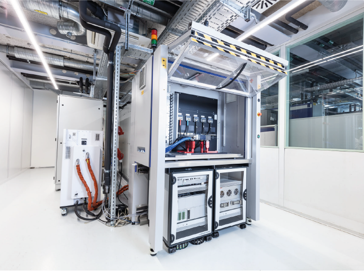
E-Motor Emulation
Use Cases

Use Case 1
Concurrent Engineering
How can you test your inverter when e-motor and gearbox are not yet available?
Usually, there are different development teams working on the overall powertrain design – for e-motor, for inverter, for gearbox. Each team wants to test and develop its component completely and independently, although they must ultimately interact together in a system.
The dependency for the inverter is huge, since no test can be run without an existing e-motor. In addition, the first sample of an e-motor never meets the specifications (e. g. speed, torque). Nevertheless, the inverter must already be developed to the specification of the e-motor. The goal is to achieve the lowest possible dependencies.
The AVL Inverter TS enables an accurate e-motor emulation so that no real e-motor is required, just the motor data. Only a few parameters are sufficient to start the testing process and further data can be generated by FMEA or engine parameterization.
That means that the inverter development can be done independently on the inverter test system, but in parallel to the other components. Therefore, you don’t lose too much time until the final integration of all components into one powertrain needs to be completed.
Use Case 2
Saving Battery Costs
How can the powertrain of an electric vehicle be optimized?
The range of an internal combustion vehicle can be extended via a larger tank. Similarly, the battery capacity of an electrified vehicle would have to be increased to enable a greater driving range. However, this is very expensive as battery costs are high.
It is important to know that every component in the powertrain loses energy (mostly in the form of heat). If the efficiency of the powertrain is improved, it is possible to keep the range constant with a smaller battery. This can be realized by increasing efficiency through optimized control methods of the inverter.
The AVL Inverter TS is the right tool to optimize the inverter’s control strategy and this leads to an overall increased efficiency of the complete powertrain. The effects of such an increased efficiency are cost savings in battery design or increased driving range.
That means, by optimizing the inverter’s operating strategy, our customers can save also money for other components – as you can also draw conclusions about the e-motor or the battery management system. Moreover, it is always a question of the overall drivetrain efficiency and the single components’ interplay to offer a cost-optimized vehicle to the final customer.
Use Case 3
Handling of E-Motor Manufacturing Tolerances
How can manufacturing tolerances of the e-motor be handled in the real vehicle?
During the manufacturing of the e-motors, there is always a tolerance range which is often up to about ± 10 % of the nominal value. These tolerances come from the treatment and aging of the production tools that are used during the manufacturing process.
Reducing or avoiding tolerance ranges would lead to higher production costs as the tools would have to be replaced earlier. But even worse, tolerances lead to control problems within the drivetrain and possibly to failures.
The motor tolerances are never completely known, but the specified manufacturing tolerances can be assumed for testing with the AVL Inverter TS and a real inverter. How does this work in detail?
In FEM simulations, the known variations can be specifically introduced. The characteristic diagrams used in the test system are then generated in a targeted manner and thus represent these tolerances. Basically, the point is that you can parameterize the test system so that the mapping of the furthest nominal e-motor is allowed. On the Inverter TS, the inverter is always protected – and you can optimize it quickly and easily for any e-motor without the risk of damaging the unit under test.
This results in a perfect driving experience for the driver – despite existing e-motor tolerances or the requirement to avoid them.
Use Case 4
Testing Inverter Failure Handling
How can you evaluate the inverter´s failure response in case of different failure situations?
In general, the testing of inverter failure reactions on a rotating testbed with a real e-motor is either very limited or dangerous, possibly leading to the destruction of the inverter and electric motor.
In addition, some failure situations can even not be done in a realistic test setup and lead to wrong results. These failures may range from cable breaks and short circuits to rotor sensor and e-motor faults.
With the AVL Inverter TS, all kind of failure tests – that might occur in a real vehicle where the inverter needs to react properly – can be performed. The Failure Emulation Cabinet (FEC) offers a simple, safe and reproducible emulation of fault scenarios in the high-voltage circuit. Based on the diagnosis of the inverter response, an ideal vehicle behavior in these situations can be realized.


